|
![[Under Construction]](images/undercon.gif)


| |
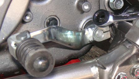
balancer adjustment lever aka doohickey*
*Important note! Any balancer parts purchased from studebaker, mashonline, or
klr650.com after late May of 2008 are not genuine Eagle parts. Genuine
Eagle levers/doohickies are H900 condition, and
much stronger than the H1150 condition currently advertised by KLR650.com. The torsion spring that hooks into the adjustment slot is
a 100 percent Eagle design. I suggest you always insist on genuine Eagle parts. I'm
glad to support Eagle parts. If your parts are not genuine Eagle please get your
support from the people that made them. All the best!
We'll start with a very popular upgrade to the KLR650. The factory balancer
system adjustment lever almost never works properly (in my experience), and
sometimes fractures. This is never a good thing inside an engine. (Sometimes the
tensioning spring breaks, or is limp, too.) Most people
report reduced vibration and noise from the engine after doing the upgrade.
If you decide to do the upgrade, examine the parts as you remove them from
the engine, to be sure you understand what you are doing, as well as how the
parts work together.
After you click on one of the pic's to expand it, you can use your back arrow
to come back.
I'm going to paste my text on how to do this upgrade for right now, and will
add pictures soon. (It's a little long, but I want to be sure it's as clear as
possible.) There are three other sites that I can think of right now that also
have instructions on how to do this. Look at all of them, if you can. My
instructions may or may not be the best for you, but I hope it helps......
Balancer Lever Replacement Outline
Set up: much easier if you can drain the oil. It can be done on the side stand,
but easier on a center stand or lift. It helps to have clean newspaper or
cardboard to set parts on, and paper towels, solvent, etc. Have the factory
manual handy, and VERIFY EVERYTHING AS YOU GO!
If you use the "lean the bike to the right" method, it helps a lot to have a long flexible shaft magnet before you start. That way things won't fall down in the
case, and you won't need to use the magnet to fish them out. :-)
Read the directions all the way through before starting. YOU NEED TO HAVE THE
FACTORY MANUAL FOR YOUR BIKE, TOO! CONSULT IT OFTEN, DOUBLE CHECK EVERY THING AS
YOU GO!
Procedure:
Put the bike up on the lift, or center stand, if you have one.
Drain the oil, unless you are leaning the bike to the right. Put the plug back
in after draining!
Remove the bash/skid plate. If you have an aftermarket plate that is difficult
to remove, you will need to at least lower the left side enough to remove the
side cases. Factory plate use 10mm socket, ratchet, remove 3 bolts. Don’t lose
the spacers that keep the plastic from being crushed. The bolt up in the front
is slightly shorter than the others. 2008 note: 4 bolts, using an 8mm socket to
remove.
Remove the countershaft sprocket cover. Use 10mm socket, extension, ratchet.
Remove 3 bolts.

Pull the green neutral wire off the stud in the case. Use fingers or pliers, gently.
Wiggle neutral wire and harness for stator out of the channel in the case, ahead
of the countershaft sprocket.

Remove the shift lever. Use 10mm open or box end wrench. Hint: mark where it
lines up on the outer case, before you take it off. There is also a small dimple
on the generator case cover that's usually about the middle of the lever. A 10mm
ratcheting box wrench is the tool of choice
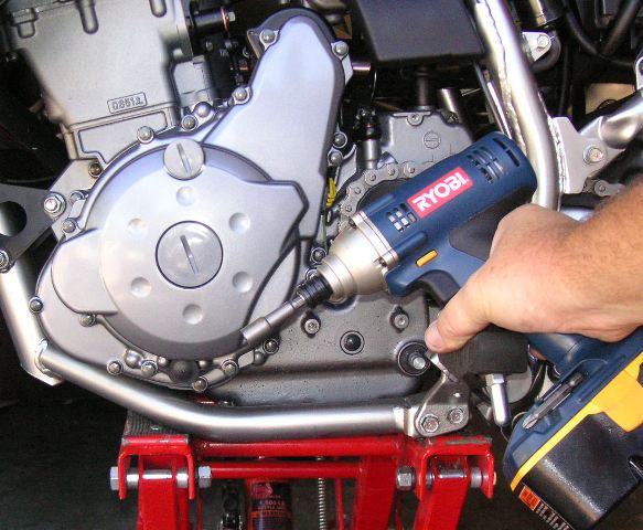
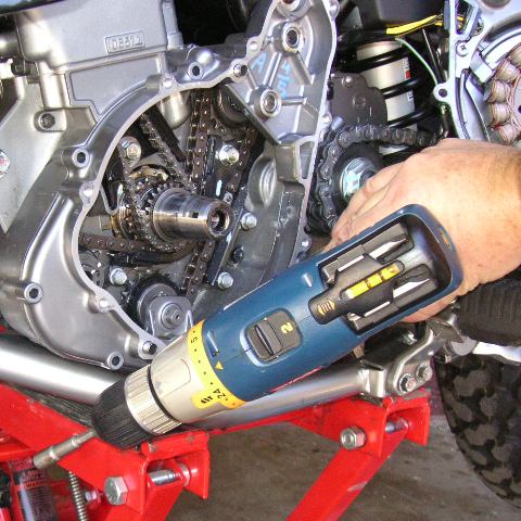
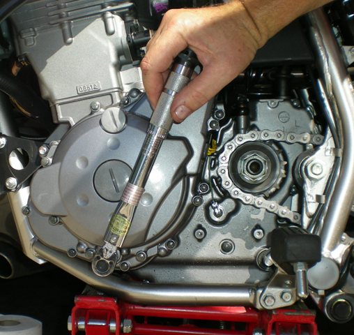
Loosen the bolts around the outer left side case. Hint: You can save time by
just breaking the bolts loose with an 8mm socket, then use a cordless drill with
an 8mm (or 5/16) driver to spin them the rest of the way out. In the pic I'm
using an 18 volt impact driver - for removal only!

In this pic the bolts are removed but I haven't yet remove the green neutral
wire.

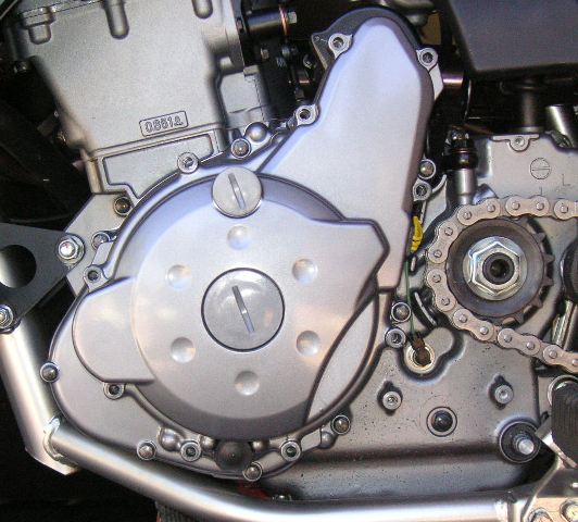
Carefully pull the
outer case straight out - you will feel the magnetic pull from the stator. You
also need to be aware of the wiring harness leading to this case - the wires you
wiggled out of the case previously. DO NOT remove the rubber plug and wiring
harness from the left side case. You just need enough play to get this case out
of the way. I like to use a piece of #10 or #12 wire looped around the right
side footpeg, then over the seat, to hang the case just out of the way above the
left side footpeg, or a bungee cord. Hint: If you carefully remove the case,
pulling it straight out, the gasket is more likely to be re-usable.

In the above pic you can see the neutral wire has been removed. The case has
been swung over and is resting on the footpeg.
Remove the 2 sets of cluster gears that are now visible upper right. Notice which
set goes where, before you lay them down on a clean surface. (all is not lost if
you forget - they will only go back in 1 way) There are inner and outer washers
for each gear set. One of the sets is fixed. The other set has 2 needle bearings
inside it, as well as the inner and outer washer. The pin it rides on comes out
of the case, easily. It does not matter which end of the pin goes into the case
first.
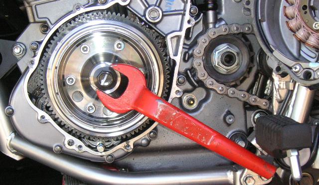
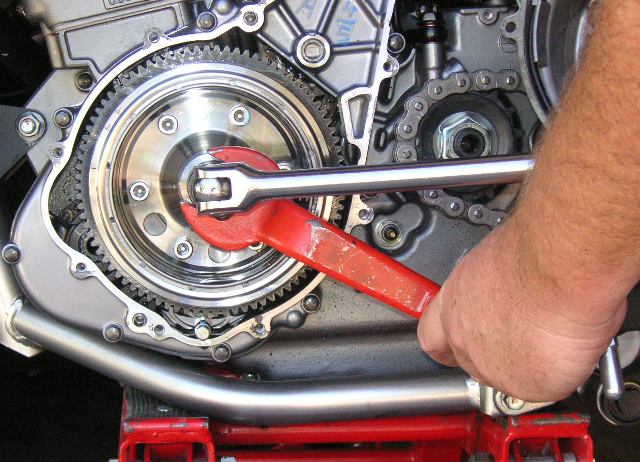
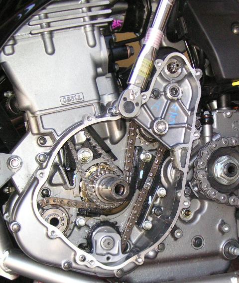
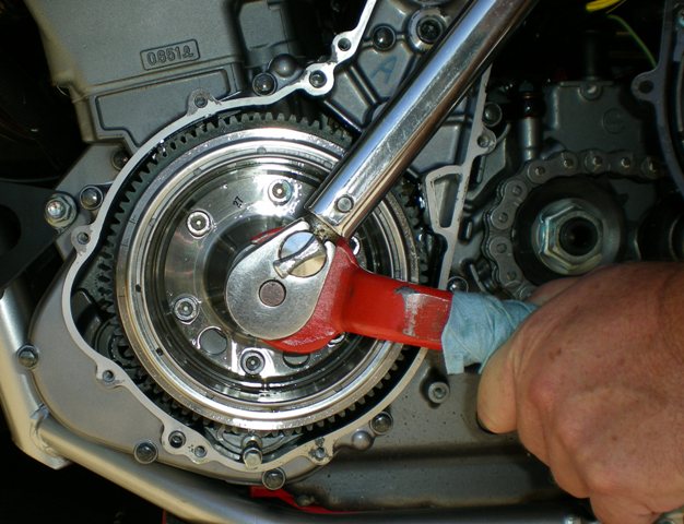
You now use the rotor holder wrench, 19mm socket (good quality), and a 18” or
longer breaker. Fit the rotor holder to the rotor, and rotate it around so it’s
stopped by the footpegs, or hiway pegs.

Then put the 19mm socket and breaker bar
on the rotor bolt. Loosen and remove the rotor bolt, by turning it
counter-clockwise. It may take some effort, as it was supposed to be torqued to
130 ft/lbs.

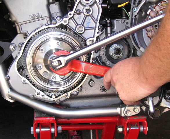
Move the holder to the other side of whatever peg you used to stop the holder
before. Grease or oil the threads and end of the rotor puller. Screw it into the
rotor until it stops against the end of the crank. Use the breaker bar and
either a 19mm or a 3/4" socket to break the rotor loose from the crank. You can see the
rotor holder wrench is now on top of the footpeg. Note: early versions of the
Eagle rotor puller have a hex size of 22mm or 7/8."

HINT: after you
break the rotor loose, unscrew the puller. Keep the rotor pushed against the
crank by hand, and turn it so the key slot in the rotor is close to straight up.
CAREFULLY remove the rotor. Watch for the key in the crank, that locates the
rotor. If all the parts come loose, including the starter gear, the key may come
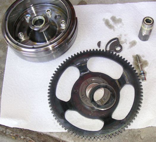
out and be inside this assembly. From outside to inside, here is the list of
parts that can be removed, or come loose, all the way back to the chain sprocket
on the crank: rotor, key, thin washer, starter gear, 2 thick washers. Try not to
drop parts into the engine. Usually, the 2 thick washers will stay on the crank.

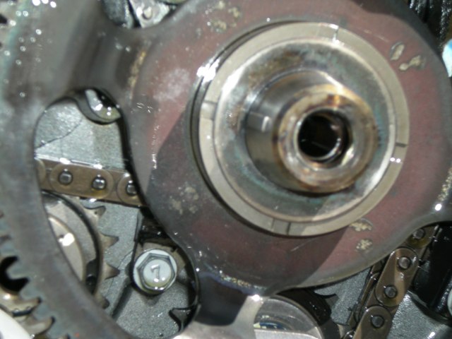
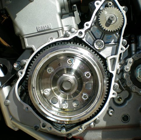
The pic below shows the 2008 rotor. Yours will look different if it's an
earlier bike.

You can stuff rags or paper towels into the openings in the bottom of the
engine. It’s not the end of the world if you do drop something - just be sure to
get everything back in the right place. Use a flexible magnet to fish
them out. You can get a good one (flexible aluminum wire) at True Value. Use a 8mm socket and ratchet to remove
the balancer adjustment bolt and washer (if you have a pre ‘96, no washer yet).
Remove the balancer adjustment lever from the eccentric shaft.
Use the 8mm socket and ratchet to loosen and remove the bolts holding the inner
case (called generator case cover by Kawasaki). Don’t forget the bolt that is inside of the case, where the 2 cluster gears for the starter were. This
bolt is slightly shorter than the others, so keep it separate. Remove this case.
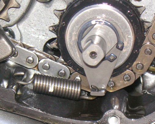
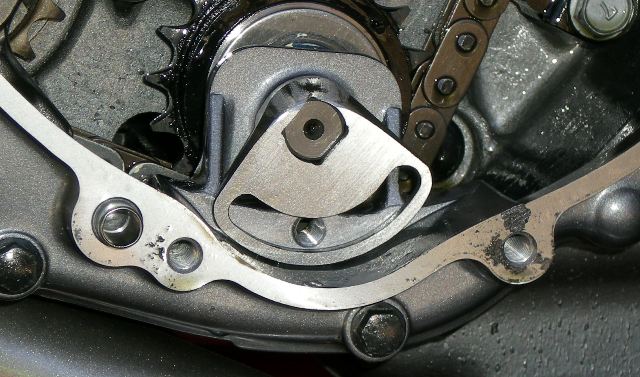
This is actually a ready to re-install shot, but you can see what's going on.

Often the case sticks around the starter motor, it helps to have a padded pliers
handle to gently pop it loose. The other place it tries to stick is around the
balancer eccentric shaft. DON'T LET THE IDLER SHAFT - THE SHAFT THE OLD LEVER
WAS ON - COME OUT WITH THE CASE!!! KEEP IT PUSHED BACK IN AS YOU REMOVE THIS
CASE. If it does come out, all is not lost, you'll just have to put the parts
back in. (see end of this document) Just wiggle the case straight out using a
little finesse. Sometimes I keep a thumb on the shaft to keep it in place, and
provide leverage as I wiggle the case off. Hint: as above, if you can keep the
case fairly straight as you remove it, the gasket is more likely to be
re-usable. The spring in the pic is the 2008 factory spring. You can see the
attach or anchor peg for it behind the gasket. This 2008 bike has 327 miles on it at
the time of photo. Factory spring is too long.

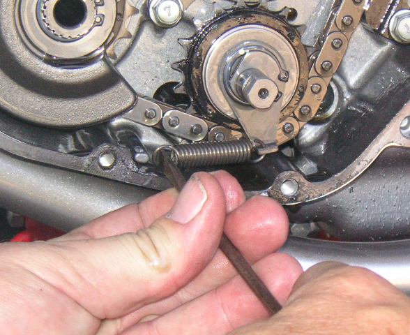
You can now remove and replace the balancer adjustment spring. If your kit came
with 2 springs, try the long spring first. I recommend about 8 to 10mm stretch
from the relaxed position (5/16 to 3/8 inch), or space between each coil of the
spring. Be sure to keep the eccentric balancer shaft assembly pushed back into
the case as you handle these parts.
If you are installing the torsion spring refer to the second article for
additional instructions. You only use the torsion spring or the extension
spring. You don't need both.


Keep everything clean as you put it all back together.
Install the inner case. If you think you need it, put a little sealer on the
case surfaces as you re-assemble. Carefully push it onto the starter and
balancer eccentric shaft. It helps to have the 2 locating dowels pins in the
engine cases. If you are putting a new gasket here, put it on the engine cases,
too. The dowel pins will help it stay aligned. Clean the bolts of any corrosion
before installing them. Remember the short bolt goes up by the starter. Torque
them to 69 in/lbs. I cheat a little here. I use a drill/driver with an
adjustable clutch to drive these screws, with the clutch on the lowest setting.
The a few seconds with the torque wrench, and I'm good to go.

Put the new, improved balancer lever on the eccentric shaft. At this point,
if you are upgrading a 2008/9, install the supplied washer onto the adjustment
bolt. If your adjustment bolt already has the washer on it, just leave it there, you are good. If you have an early klr650 without a washer, and don't have the later bolt handy, don't worry about it, you'll be ok. You could always remove the outer case and change the bolt later without needing to pull the rotor. Run the adjuster
bolt and washer in until it touches, then back off a turn (if you have the early
bike, you should install the later bolt with washer - this will spread out the
pressure on the adjustment lever). You will tighten the balancer lever
adjustment bolt later with the outer case bolts.

Be sure the 2 thick washers are on the crank, lightly oiled. Install the starter
gear, be sure the crank and starter gear bore are oiled. Install the thin washer
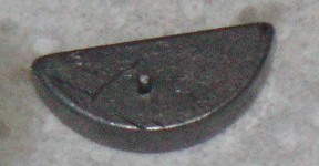
on the crank, with oil on it. Centerpunch the side of the key, so it will stay
put in the crank, during rotor installation.


Install the key into the crank,
lightly tapping it down to seat it if necessary. Clean the tapered portion of
the crank with a clean paper towel. Clean the mating tapered bore in the rotor
with a clean paper towel. Install the rotor - BIG HINT - as you install it onto
the crank, rotate the starter gear so you can easily align the rotor, crank, and
key. The starter gear will rotate easily one way - clockwise. It’s easier than
it sounds. You will feel the rotor seat, and align on the crank and key.
Install a new rotor bolt. Tighten it to 85 ft/lbs, using the rotor holder, a
19mm socket, and a torque wrench. Right now, before you do anything else, be sure you can turn the big starter gear clockwise with one finger. It won't quote spin, but you should be able to turn it with one finger. If you can't, stop here. Pull the rotor, and see what is going. Likely the key isn't properly aligned in the rotor slot. If you can turn the big gear clockwise with one finger, loosen the bolt slightly, then torque to final
value. The factory manual says 130 ft/lbs. For the 2008 and later engines the
final torque value is 144 ft-lbs. IMPORTANT NOTE: some years (in my
experience 1987 to 1995) have less endplay between the back rotor face, thin
washer, and starter gear. Not every bike has exhibited this condition, so I'll
tell you how I deal with it. Once I have torqued to 85 lbs, and loosened the
bolt a little, go back up to 100 ft lbs. Wiggle the large starter gear in and
out, turning it at the same time, to be sure there is a little end play behind
the rotor. Go up 5 ft lbs, and repeat. Do this until you think you are running
out of endplay. When you spin the starter gear clockwise, if you feel drag
caused by friction, loosen the rotor bolt, and re-torque to 5 or 10 lbs less
than where you last were. This starter gear will not spin freely, but should
turn easily clockwise with 1 finger. This is one of the things I have learned -
I've helped or personally done this upgrade to over 400
KLR650's at the time this is updated.

Clean the case surfaces, be sure the dowel pins are in one case - inner or outer
- life is easier that way. Use gasket sealer if necessary. Install the 2 cluster
gear sets for the starter - remember the inner and outer washers. The fixed set
- upper - goes in first, the larger gear fits the starter gear teeth. Then
install the other set, with the washer inside against the case on the pin, the 2
bearings, the 2 gears, the outer washer.

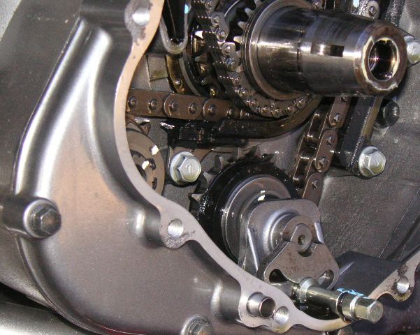
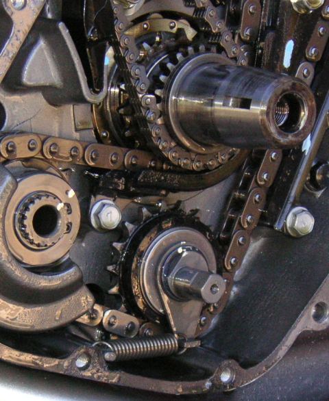
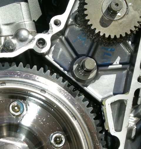
You can see in the pic below I installed the pin, inner thrust washer, and
the 2 bearings. Then install the gearset and outer thrust washer.
See below for special conditions regarding all 2008 and early 2009 models.


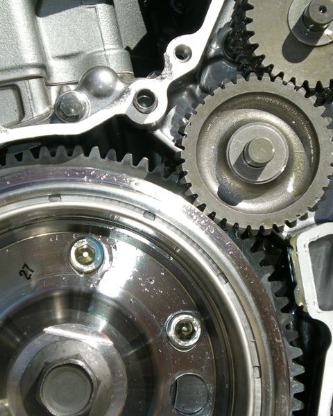
You may need to turn the big starter
gear on the crank clockwise just a bit to allow the gears to seat. Install the outer case.

Spin in the bolts, then torque to 69 in/lbs. Torque the balancer adjustment bolt
to 69 in/lbs.
Wiggle the wiring back into the slot in front of the countershaft sprocket.
Install the neutral wire to the case. Install the shift lever. Install the
countershaft cover. Install the rubber cover for the balancer adjustment bolt.
Install the skid/bash plate. Pour your favorite oil into the engine.
Remember, this is just a supplement to the factory manual. If you find another
way to do this, or something is missing, please let me know so I can update the
instructions.
I think you’re done!
PUTTING THE IDLER SHAFT BACK IN IF IT CAME OUT WITH THE INNER CASE-----there
are several parts in this little assembly. There is the fat washer that goes
against the inside engine case, then the sprocket and needle bearing, then the
outer washer. I'm not going to tell you about the spring lever still on the
idler shaft, as it's held on with a circlip. The fat washer, smaller in diameter
than the outer one, is the one usually dropped down in the case. You may need a
magnet to fish it out of the bottom of the crankcase. Easiest way to recover
here in my experience is: Stack the parts on your strong hand pinkie, outer
washer first, then needle bearing and sprocket, then inner fat washer. Remember
the recess in the sprocket goes toward the center of the engine. Put the
sprocket on the chain, carefully, while keeping these parts on your pinkie. Push
the end of your pinkie onto the hole in the inner engine case where all the
parts go, as you put the sprocket on the chain. After you found the hole, and
got everything pretty closely lined up, use your other hand to hold this
assembly against the case, to keep from dropping parts by friction. Pull your
pinkie out, reach down, grab the idler shaft, and it'll usually go right in. You
might need to rotate it back and forth just a little, to get it to slide back
into place. Now, choose the spring you are going to use, and find where you were
in the instructions above!
Special note regarding 2008 and early 2009 models:
If you have a 2008 or early 2009 KLR650 the lower of the two holes for the
gearsets in the outer case has a flaw - it should have a shoulder in the hole to
keep the dowel pin from going too far into the outer case. This pertains to all
2008 and 2009 models with a VIN below 20800. This is the last 5 numbers of the
VIN. If your VIN is slightly higher than this I would double check to make sure.
This is easily fixed. Just put a spacer in the hole in the outer cover. A 3/8"
diameter by 3/8" long spacer works fine. I'll add pic's in a day or two.
If you get stuck, or have any questions, call me 619 697 1674 shop. 619 261 1281
cell.
all the best,
Mike
|